Using the fact that the height h of an observed landmark is constant for any angle of the landmark plane (for a constant distance d), and the width w variates with the angle, the observed angle of the landmark plane can be calculated as:
α = acos(w/h)
Wednesday, June 30, 2010
Friday, June 11, 2010
Landmark recognition
I'm now working on implementing some of my master thesis I didn't have time to finish. Landmark recognition and distance to landmark, angle to landmark is now working, and only needs some tuning - the pixel classification is a bit too greedy.
Monday, May 24, 2010
RoboCup 2010
So I came in as number 8 in the DTU RoboCup 2010, which I was quite happy about, given the amount of time I had to put in the project. Here is a video of Ridgy in the final round:
Tuesday, April 13, 2010
Wednesday, March 24, 2010
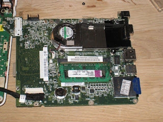
Acer Aspire One RAM mod
I'm using an Acer Aspire One to control my robot. I'm coding using Eclipse, but the 512 MB RAM in the Aspire is too small, and it swaps. Swapping on the flash drive is very slow, so I finally took the courage to upgrade it to 1.5 GB, following this nice guide: http://tnkgrl.wordpress.com/2008/08/14/modding-the-acer-aspire-one-bluetooth/ .
 It worked!
 It worked!
Sunday, March 14, 2010
6 servos and a gate sensor

While I had my circuit board disconnected to fix the tachometers I also added support for an extra servo motor, so the board can now control 6 servos. I've also added a gate sensor since I first blogged about the robot. The gate sensor is nothing more than a switch on a stick.
I need to shorten that USB wire from the camera...
Tachometer blues

So my tachometers suddenly started acting weird. When on the edge between black and white, the tachometers counted up like crazy. I figured the Schmitt triggers on the input pens on the Atmega must be a little too sensitive. They have a hysteresis of only 0.25 volts @ a supply voltage of 5V, thats a bit in the low end. So I added a 4093 quad nand schmitt trigger IC (hysteresis 0.9V), and after a little confusion (forgot one single connection on the circuit board - that gave really odd results), the tachometers now run flawlessly.
Sunday, February 07, 2010
The first video of my new robot
My new robot can now follow a line pretty robust. Here is the first video of it:
This is what the robot "sees" when following the line:
The red and blue pixels marks the left and right edges of the line. I don't use that information yet and it is not tuned very well. The green pixels marks the center of the line. The yellow line is the result of the processing of the green pixels. This is the only information the robot uses to steer at the moment. It doesn't recognize intersections or forks on the line and doesn't even recognize that the line ends. More to come later...
A picture of the robot:

Subscribe to:
Comments (Atom)


